11 Results
View results:
Sort by:

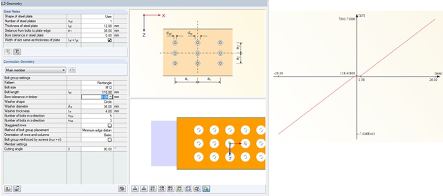
Custom sections are often required in cold-formed steel design. In RFEM 6, the custom section can be created using one of the “Thin-Walled” sections available in the library. For other sections that do not meet any of the 14 available cold-formed shapes, the sections can be created and imported from the standalone program, RSECTION. For general information on AISI steel design in RFEM 6, refer to the Knowledge Base article provided at the end of the page.

In RFEM, RSTAB, and SHAPE-THIN, you can create user-defined print templates ("Printout Report Template") and printout headers ("Report Headers"). These templates can also be transferred to other computers and used there.

RFEM 5 allows you to use many different member nonlinearities for designing a model. In the following text, we look at an example of the use of the "slippage" member nonlinearity. The example is a simplified model of a concrete manhole with a square plan view.
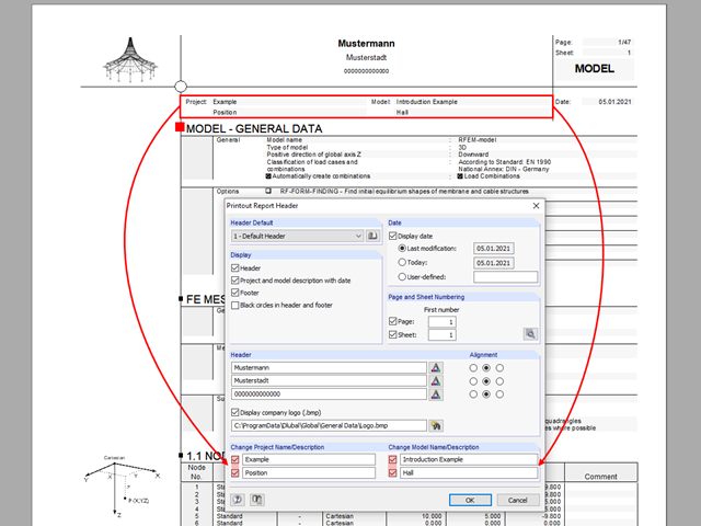
The name of the project/model from the General Data is shown in the header of the printout report by default. In RFEM 5 and RSTAB 8, the model name can be changed manually in the printout report independently of the actual name.
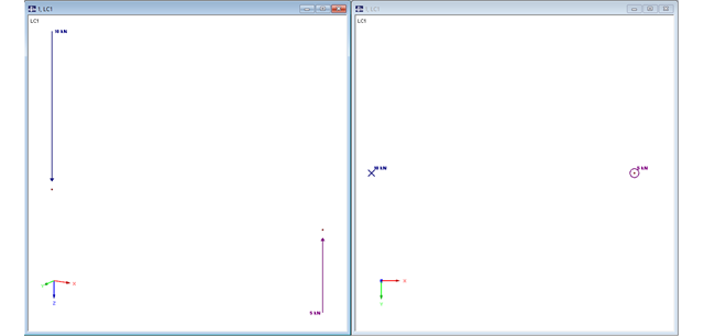
In RFEM, structures can be modeled and analyzed in a spatial environment. The permanent 3D visualization helps you to better understand complex models and to represent the force flux. However, you can switch from a spatial mode to a planar sheet mode in the documentation of a calculation. To do this, you have to describe the spatial calculation of the structure with all the necessary properties on "flat" paper pages for an independent reader. Usually, you try to display the load actions and the corresponding results by using an orthogonal view of the substructure of the entire structure. Obviously, the load symbols depicted in the 3D mode in a view perpendicular to the load become unrecognizable due the missing expansion. In order to be still able to create a clear representation of all information, the corresponding adjustments are available in RFEM.
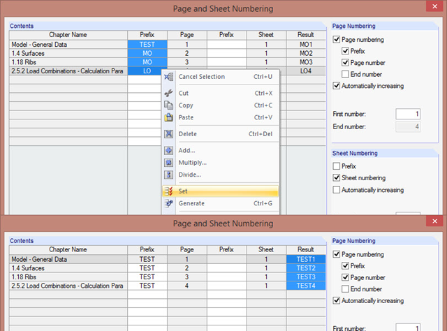
The "Page and Sheet Numbering" dialog box allows you to add a prefix to page and sheet numbering. It can be an abbreviation that specifies by chapter all model data in the numbering (for example, with "MO").
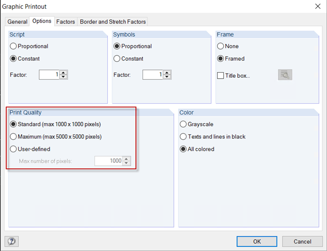
For a structural analysis printout in the usual DIN A4 page format, the default settings of 1,000 x 1,000 pixels graphic quality are completely sufficient. However, if the printout should be on a larger page format, you can increase the print quality to a maximum of 5,000 x 5,000 pixels in the Graphic Printout options, or specify a user‑defined value.
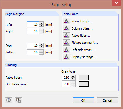
The layout of a printout report can be adjusted by changing fonts, font colors, page margins, and table shading.
In RF-JOINTS Timber – Steel to Timber, you can consider the possible minimum slippage of bolts in the case of guide pins. In RFEM, this slippage is taken into account using the flexibility in member end releases.
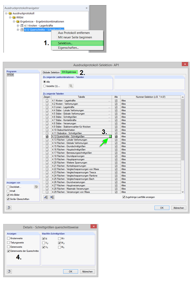
In order to reduce the number of pages in a printout report or to obtain shorter and clearer result tables, you can use filters for the printout report tables using individual detailed settings.
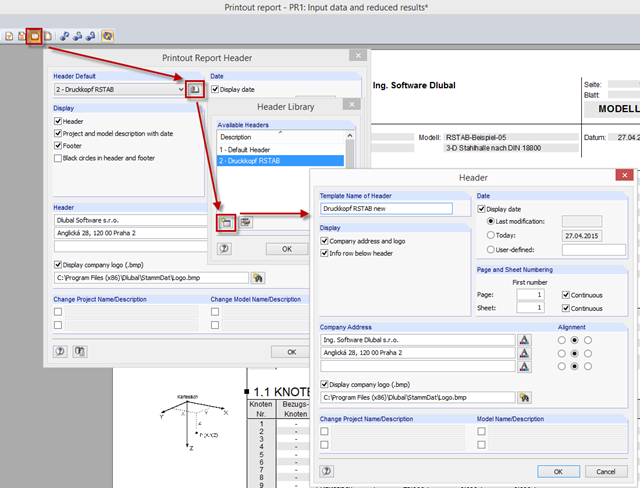
Sometimes, it is necessary to change the printout report header in a 3D PDF. To do this, adjust the header of the normal printout report. The new printout report header is then also applied for the 3D PDF.